RR&Co Computor Control: Discussion
Posted
Full Member
Post any questions arising from "First Steps with RR&Co"
[user=450]wogga[/user] wrote:I'm not doing much with TC at the moment, other than controlling routes, but I can tell you that the "expanded engine" window that Brian shows is actually a "Traffic Control" window. Once you have it open you can enter specific block details showing engine movements, etc. In Silver I can only open one, but looking at Brian's screen, it would seem that in Gold you can have several open at the same time.Can tell me how you get the expanded engine window?

Posted
Full Member
Posted

Full Member
Hi Pete,
The multiple CIs and B & S markers in the end blocks are simply to stop the train with the loco near the buffers and the replacement engine at the rear to couple. On the layout I expect to need several groups of these for trains of different set lengths. The short CI section (12" - 15") at the departure end is for convenience: Those sections on the layout are on a different baseboard to the main platforms and that board has its own detector module. They have the advantage of avoiding the need for a VC to show entry of the second engine. I will need to experiment live for stopping "Tail of train" at markers - the sim does not show what will happen. The storage loops will be one block per engine or train so everything will shuffle up when a train leaves a front block and TC can track them all. The front blocks will be the finish blocks for the departure schedule(s) and start blocks for Arrival schedules.
Brian i think using multiple CI's is an expensive work around? i use one set of B&S markers to stop the train infront of the buffers and a second set allocated to the loco that backs in to couple see below. i will try to have trains of equal length to control the number of BS markers required (cheating?)

I use join and seperate commands in the operations list at the start of the relief engine schedules, I do this with only one CI in the block?
Your thoughts. I will try those windows later.
Brian there is DCC show over at Rawtenstall this weelend i am thinkiing of going..are you and hello is Matt there?
Regards
Pete.
ECOS2 with RR&Co Traincontroller and a load of other electronics so i can sit back and watch the trains go by.
Pete.
ECOS2 with RR&Co Traincontroller and a load of other electronics so i can sit back and watch the trains go by.
Posted

Full Member
The multiple CIs and B & S markers in the end blocks are simply to stop the train with the loco near the buffers and the replacement engine at the rear to couple. On the layout I expect to need several groups of these for trains of different set lengths. The short CI section (12" - 15") at the departure end is for convenience: Those sections on the layout are on a different baseboard to the main platforms and that board has its own detector module. They have the advantage of avoiding the need for a VC to show entry of the second engine.
I have a feeling I am going to be hitting those red faced icons again…..in fact here is one to establish credit :oops:
I am assuming you are using, or planning to use, occupancy indicators like the Lenz LR 101s. If you were using magnets and reeds ie a true contact indicator then I believe you need 3 per block
So assuming occupancy indicators I dont understand how 2 would work in a block……or is the block divided into electrically isolated sections……in which case why not have 2 blocks ……..I suspect I am missing the obvious somewhere
But, in any event, I think Pete has a vey good point regarding cost…….4 BR 101s @ $20 and 1 LR 101 @ $65 : $145/8 = $18 (10 UK Pounds?) per detector………….so one per block has to do it for me…….I have just ordered the ones I need to complete the layout…….. fortunately the $Cdn is almost par with the $US…….it still cost an arm and a leg
Thats a great shot Pete……can I use it in the tutorial?[user=449]brianpr1[/user] wrote:
Brian i think using multiple CI's is an expensive work around? i use one set of B&S markers to stop the train infront of the buffers and a second set allocated to the loco that backs in to couple see below. i will try to have trains of equal length to control the number of BS markers required (cheating?)
I use join and seperate commands in the operations list at the start of the relief engine schedules, I do this with only one CI in the block?
Does this work in real life Pete? I will have to check my files I have a feeling I [join] in the coupling schedule and [separate] in the departure schedule………….and there was some reason for this…..I will check I am not near my layout file
Regards
Posted
Full Member
Thats a great shot Pete……can I use it in the tutorial?
John i am honoured you want any my stuff :oops: of course feel free to take whatever.
Re the the join/seperate, yes it works a treat, my arriving train sched stops at the buffers and the finish operation is the kadee shuffle alla your goodself. I did try a seperate after but it didn't work.
So physically the engine and coach is now split but as far as TC is concerned they are not! I then start my relief engine schedule which has the join/seperate routine, as above, as its finish operation. I set the rules so the engine can enter the occupied block for joining. The engine enters the block and stops at the second set of B&S markers and then TC does its bit, joins and seperates on cue.
John i am sure you told me this???
Regards
Pete.
ECOS2 with RR&Co Traincontroller and a load of other electronics so i can sit back and watch the trains go by.
Pete.
ECOS2 with RR&Co Traincontroller and a load of other electronics so i can sit back and watch the trains go by.
Posted
Full Member
John i am sure you told me this???
:oops::oops::oops: You know I think you are correct……the whole time I was typing my first post I kept thinking….."no this is correct"………………my only excuse(s)……old age……I was late……the dog was being sick:twisted::twisted:
Moral check before you type……my apologies
Posted
Full Member

Regards
Pete.
ECOS2 with RR&Co Traincontroller and a load of other electronics so i can sit back and watch the trains go by.
Pete.
ECOS2 with RR&Co Traincontroller and a load of other electronics so i can sit back and watch the trains go by.
Posted
Full Member
Sounds like a man that is overdue some loco profiling
Nice one
Cant get into the railway room……read a post titled "Magic Water" that hopefully I will send tomorrow
Posted
Guest user
I think the difference is that you need the block to the rear for other purposes. My next "necessary" block is the last block in the storage loops, so there are three, possibly four, in parallel. I can see problems with choosing between three VCs and in any case those blocks are about14 feet away from the platforms and I think that may be too far for the VC timer to be accurate.
I'm off now, I will add a bit more about cost when I get back.
Posted
Guest user
Another thought about VCs - If the schedule starts in the same block as the VC is referenced to then I don't believe the VC will work, the train has to run through the ref. block. That means I could not use them.
Pete,
I did not know about Rawtenstall, but I would like to go. What day and time are you planning to be there? We could meet up.
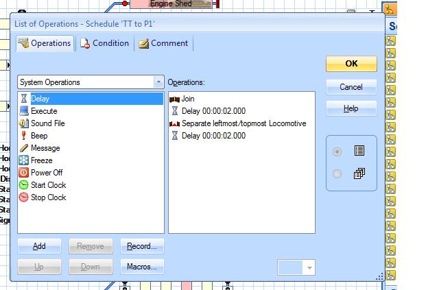
On the join/separate routine, I am still handicapped in not having enough operational blocks to try it for real. On the sim I check for each engine/train "enable join by train tracking". That seems to remove the need for a join command in each schedule, so the finish operations for the light engine are: Separate xxxxmost locomotive, Delay xxx mS, Activate the departure schedule (bearing in mind John's finding that a successor starts before the separate has happened, so both engines would move off together).
I'm still thinking about variations on the two CIs in one block. I will come back on that one.
Cost: I've been avoiding this, but I guess I have to out myself as a closet geek. I joined MERG almost exactly three years ago, with no previous history of using electronics, and I became addicted. As a result, I build my own detector/s88 feedback modules. The cost in time has been enormous, but in cash they cost about £10 each, £1.25 per detector. So far I've built five of them, with another three PCBs drilled and waiting to be assembled. To my continued amazement they seem to work well. To operate points I use a servo (say £3.00), a PicAxe based driver (about 80p per servo) and a MERG accessory driver kit (about £1.50 per output). With a microswitch, the cost per point is less than £6. For signals I started by using MERG signal driver kits, but their logic is the inverse of that needed by the ECoS so I binned them and made my own, with far fewer components. They cost about 90p per signal.
Posted
Full Member
I have to go out in a few minutes, so for now I will just look at the multiple detectors story: Pete - how does TC know when the second engine has entered your block for join/separate?
Good question Brian well posed, i don't really know??? the scedule for the relief loco has the rules set to allow entry into occupied block for joining, TC knows there is an operation at hte finish for join and seperate. TC must recognise increased current flow Brian??? the relief enters the block and obeys the B&S markers allocated for that schedule and stops on the nail for coupling. It has to detect its entry on the same CI i have nowt else i never gave it a thought. Its got to recognise the current Brian.
Regards
Pete.
ECOS2 with RR&Co Traincontroller and a load of other electronics so i can sit back and watch the trains go by.
Pete.
ECOS2 with RR&Co Traincontroller and a load of other electronics so i can sit back and watch the trains go by.
Posted
Full Member
Regards
Pete.
ECOS2 with RR&Co Traincontroller and a load of other electronics so i can sit back and watch the trains go by.
Pete.
ECOS2 with RR&Co Traincontroller and a load of other electronics so i can sit back and watch the trains go by.
Posted
Guest user
Sunday at 10 sounds fine: I'll see you in the crush to get in!
Posted
Full Member
Sunday at 10 is good for me, see if Matt is availible.
Regards
Pete.
ECOS2 with RR&Co Traincontroller and a load of other electronics so i can sit back and watch the trains go by.
Pete.
ECOS2 with RR&Co Traincontroller and a load of other electronics so i can sit back and watch the trains go by.
Posted
Guest user
Posted
Full Member
Now we know you have a home electronic factoryI have to go out in a few minutes, so for now I will just look at the multiple detectors story: Pete - how does TC know when the second engine has entered your block for join/separate? I suspect you use a VC triggered from the block to the rear. Basically all I have done is move that block next to the join/separate block and amalgamate the two blocks into one, but with two CIs and two electrical sections. The train fits into the main section, the new engine into the end section, but join and separate apply to the complete block. The end section shows empty after the train has crossed into the main so the software knows (on the sim, at least) when the second engine arrives without needing a VC.
 all becomes clearer
I started going down this route but had two blocks using a CI in each. My buffer block (B) was short ……just to accommodate the uncoupled loco…….the train finished in block A did the uncouple routine and then a successor schedule moved the loco to block B………leaving the coaches in Block A ready to be coupled……worked fine but it was a little clumsy and of course involved two CIs that how I eventually dicovered the VC route
As you dont have CI constraints I think your solution is more elegant and flexible…….I had never thought of splitting a block into two detected sections. Having Block B the larger block (or in your case Section B) accommodating the entire train is clearly better
That is correct:sad: One of the more frustrating/disappointing elements about TC is that having made the switch from DC to DCC and got rid of all that section switching and being able to stable locos prototypically buffer to buffer once you get TC you have to go back to isolated sections or run through hoops with VCs with the constraint you have just noted :sad:Another thought about VCs - If the schedule starts in the same block as the VC is referenced to then I don't believe the VC will work, the train has to run through the ref. block. That means I could not use them.
I could be wrong but I think it is another example of TC's "train deduction/assumption". It knows the loco is in block A because of the contact indicator………….it is told to to activate the Virtual Contact in Block B when the train has travelled x inches and it knows when it has left Block A……in the same manner that the train stops when TC calculates it has travelled the distance specified………………but I could be wrongTC must recognise increased current flow Brian??? the relief enters the block and obeys the B&S markers allocated for that schedule and stops on the nail for coupling. It has to detect its entry on the same CI i have nowt else i never gave it a thought. Its got to recognise the current Brian.
Posted
Guest user
Basically I followed the tutorial exactly, changing only addresses and block names.
The routine works on the sim, but on the layout TC would not recognise that the second engine was in the block for join/separate.
I tried various combinations of rules, distances etc. but nothing would work.
After two days the penny dropped: There has to be a link between the VC and the block, and this is my solution:
Picking up from the tutorial where you have set the VC memory to 20sec:
Go into edit mode, on the switchboard double click on block 661. Open the block editor, highlight "insert existing contact indicator" and choose Virtual Contact. Click on the one you have made in the previous steps:

This puts a second section into the block. When the VC switches on, the new section changes from yellow to pink, and you're in!
You can drag the sizes of the two sections to whatever you want, and, better still, you can use any of the markers in it. They start to work from the position where the VC switched on, but you will need to set the VCs memory to give the train time to act on them.

I have this working for real, including a modified shuffle and raising and lowering the uncoupler ramp. Distances are inaccurate and bear no relation to measurements because I have no profiling track, but the essential part is that TC accepts the second engine and does the join and separate with it.
I hope I am not teaching you to suck eggs,
regards,
Brian
Posted
Full Member
I think you have picked up a flaw in the tutoria:oops:
When I started the tutorial I created the contact indicators and then allocated them to the blocks using "Allocate existing Indicator'" . I wanted them displayed outside so they could be activated manually
This is contrary to the way I actually do it,on my layout, where I create the block then create a new CI from the block editor so it automatically linked to the block.
When I did the tutorial for the VC although on my own layout the VC is within the block I followed the tutorial convention and created it outside the block and assumed that the reference linked it to block 661…….when I look at it closely this is not the case
It has to be placed within the block using "Allocate existing Indicator". I am surprised it works in the SIM…………which it clearly does and that nobody picked it up before
I am having an editing session tonight so I will correct it in the old tutorial…….it will be a while before I re post it
ps Have you gone off two sections per block?:???:
Regards
Posted
Guest user
It has to be placed within the block using "Allocate existing Indicator". I am surprised it works in the SIM…………which it clearly does and that nobody picked it up before
ps Have you gone off two sections per block?:???:
I'm relieved to hear that: Once again I wondered if I had missed something obvious.
The sim seems a bit quirky with two engines - the block seems to switch on and off when it shouldn't, and that possibly lets it see the second engine?
I'm using two sections per block in the platforms, but I have only one block/one CI operational outside the station and I needed to do the same exhange there to get a train to come back. The light engine from the platform runs through the end section of the platform block without stopping and that allows me to use a VC on the outbound trip.
Posted
Full Member
Traincontroller/Create Engine/Properties/Functions
This is an appendix to John tutorial section dealing with creating an engine in Traincontroller (TC).
This section deals with setting up engine functions so they can be operated by TC. For the example I will be setting up my Class 108 DMU which is fitted with a Loksound 3.5 decoder and therefore has a plethora of functions.
There are multiple of ways to operate an engine’s functions in TC; the simplest way is to activate them manually via the onscreen throttle just like a typical DCC handset.
Or via a separate pushbutton on the screen (Pushbuttons will be covered later in the tutorial).
Functions can also be activated automatically by TC, either as part of the operations within a schedule, a virtual contact or an action marker within a block, all of these will be covered later.
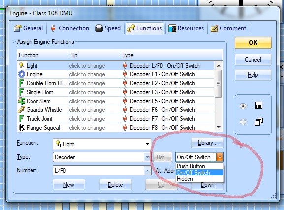
When you create an engine in TC you have plenty of information to enter about the engine in its properties box. We have covered the following tabs General Properties, Connection and have touched on Speed this section focuses on the Functions tab. When you click the Functions tab you will see a window similar to below:
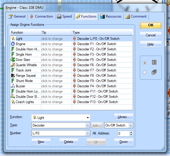
The main Window “Assign Engine Functions†is where you allocate the engines available functions and what F number they have , these are the functions programmed in the decoder and will vary from decoder to decoder e.g. a function decoder or a sound decoder.
The decoder above is for a Class 108 DMU Loksound 3.5 which is programmed with a Howe’s sound file as can be seen there are more than 10 useable functions on this particular decoder.
N.B. It is worth pointing out at this stage that TC cannot be used to change or program the functions on a decoder we are only telling TC what there is on the decoder and what F button is used to switch them.
We will cover the basic tasks here as with a lot of TC there is a multitude of options.
Ok if you click on one of the functions in the list you can edit it, here I have clicked the second one Engine
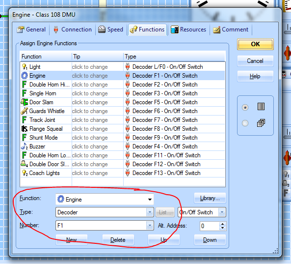
You will now see that the highlighted boxes have changed to suit, this where we tell TC what function is on what function switch.
Click the arrow to the right of the top box “Function†this will open a list of all available common functions. Select the function you want from the scrollable list.
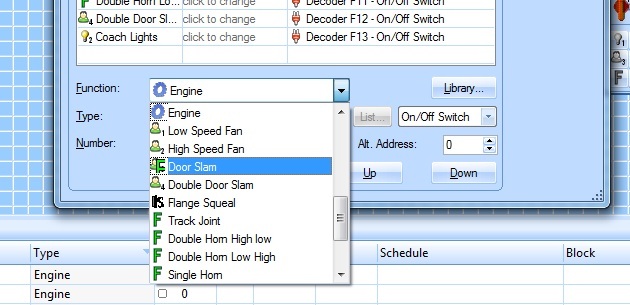
Leave the second window as decoder.
Click the arrow on the “Number Box†and from the list select the function number for that particular function which must equal what it is in the decoder programming.
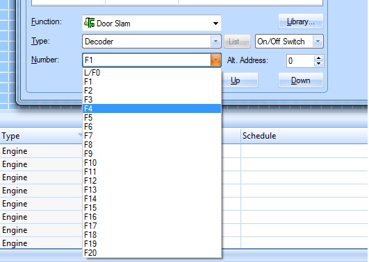
I have now allocated Door Slam to F4.
Top Tip: if you have a lot of engines with functions i.e. lights and sound try where possible to allocate a particular sound /light to the same function button on every engine e.g two tone horn on F4. Steam Whistle on F4.
The reason is when we come to make functions happen automatically in TC say by an action marker or virtual contact the same function will operate on every engine. For example if your train is approaching a level crossing and you want it to sound a warning you can allocate F4 to a virtual marker then a diesel loco can sound its horn and F4 on a steam engine could sound its whistle.
The next step is to set what type of switch the function button should act like the default setting is an “on/off switch†push it once to switch on, push again to switch off. Other options are push button which should act like a momentary contact, Hidden ignore for now. At this stage leave them as “on/off†or push button..
Do the above steps for all the remaining functions programmed on the decoder then press ok you are done.
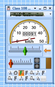
An engine which has no functions in it, the throttle will look like this:
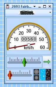
An engine with functions set as above, the throttle will look like this with all the function buttons visible:

You are done.
 Last edit: by wogga
Regards
Pete.
ECOS2 with RR&Co Traincontroller and a load of other electronics so i can sit back and watch the trains go by.
Pete.
ECOS2 with RR&Co Traincontroller and a load of other electronics so i can sit back and watch the trains go by.
1 guest and 0 members have just viewed this.