LMS ex MR 0-4-4T 1P
Posted
#218833
(In Topic #11925)

Full Member
Craftsman Kit
My strategy (if I can dignify my ramblings as such) is to try to clear some of the backlog of locos that have sat on a shelf for decades.One example is this Craftsman kit of the subject loco. It is a multimedia kit including nickel silver and brass etches along with whitemetal castings.
First off, the etches:
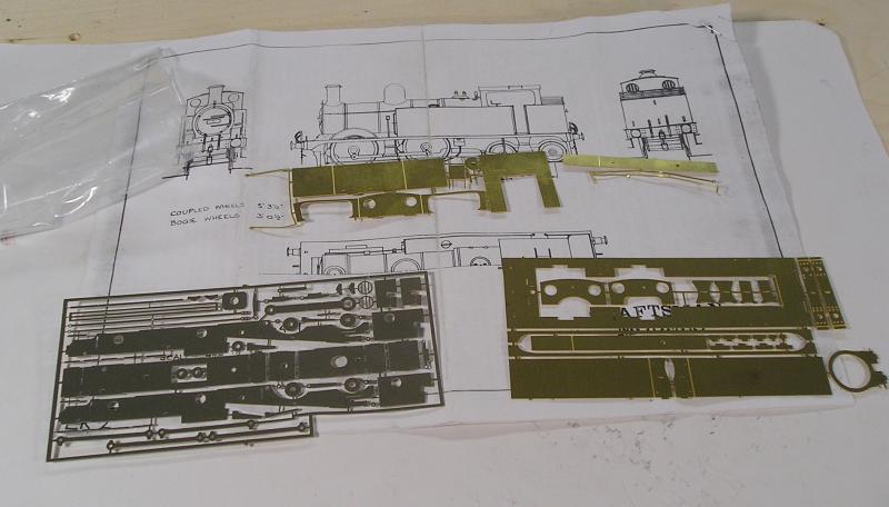
The kit shows its' age by recommending the X04 as motor, and the frames are cut out accept it - not likely methinks.
The rest of the kit:
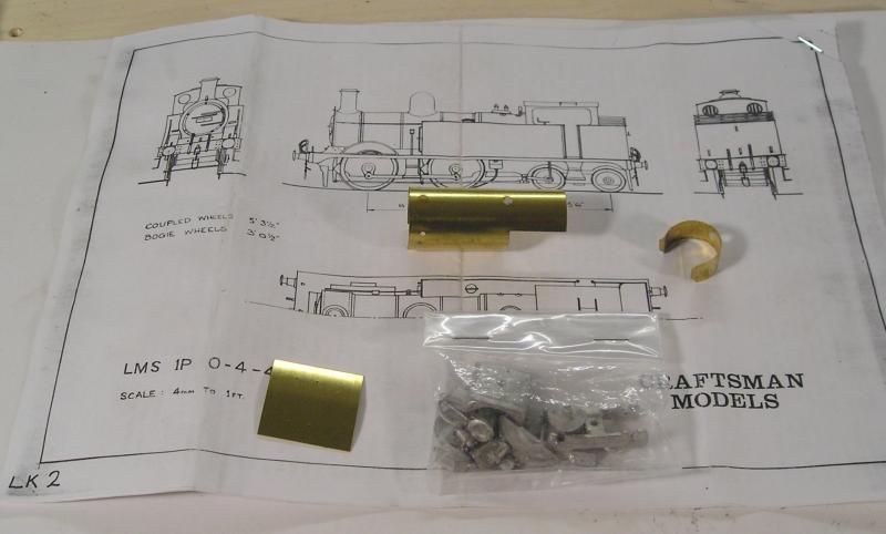
Boiler, roof and smokebox as well as a bag of castings that I haven't really examined yet.
After a day or so work, here is the state of play:
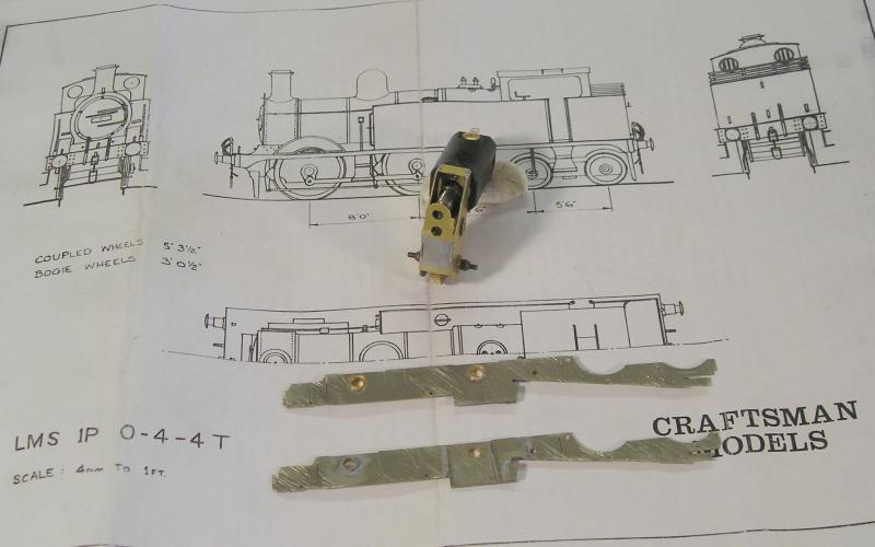
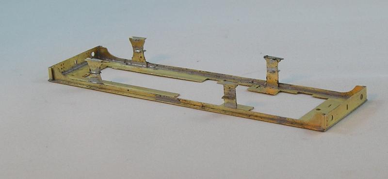
The frames have been built up with bearings and strengthening pieces around the driven axle (not sure what they'll do).
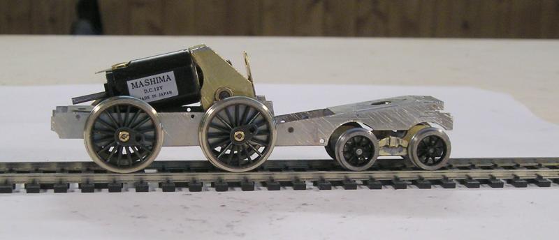
I spent quite a bit of time with the motor and gearbox. Before assembling the frames I though I'd better see if my choice will work. It is a Comet 2 stage, 38/1 GB and Mashima motor. The GB does take quite a bit of care to set up. I did one a few years that got wrecked because I didn't get the idler gear directly below the worm. This time I got it right.
This morning, I ran the system in using a DC power supply. Alternating between dry, oiled and a jewellers' rouge/oil mixture, and cleaning in between.
One issue that can arise with these GBs is that, because there's a grub screw holding the gears on their shafts, you can get a slight high spot. I always secure the worm to the motor using Loctite sleeve retainer to eliminate at least one source of high spot.
After about an hour of the process, I think I've got the system running smoothly and the high spots appear to have been improved, so I'm happy.
The drawing is to scale so I overlaid the motor/GB over it to confirm that things will fit. They appear to at this point.
John
John

Posted
Full Member
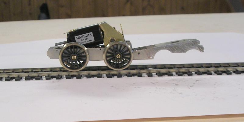
The frames are joined together with numerous spacers using tab and slot construction. As such, you should be able to get away with getting this square without any elaborate jigging. I used mine because it's there.
Because I used a different GB, I had to modify the main spacer for the final drive gear. The sloped area at the rear is supposed to take the X04.
John
John
Posted
Full Member
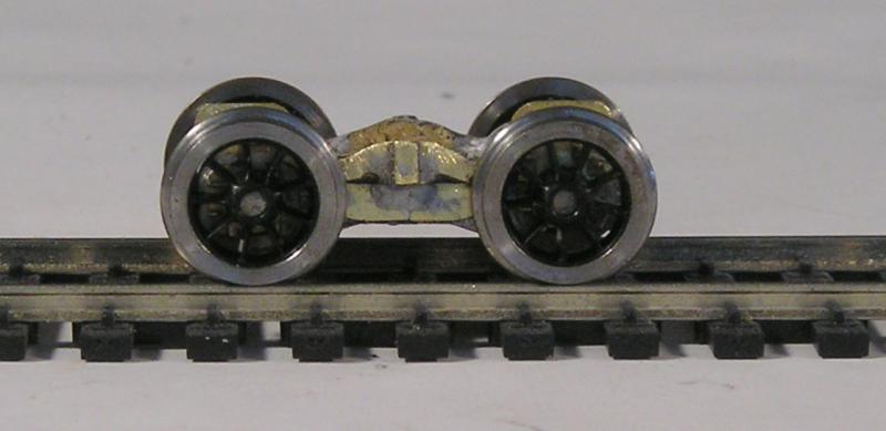
First bad news is that this locos bogie has axles 5' 6" apart whereas my kit has them at 6" 3". My approach, after having a bit of a think, was to open the slots of the base to 5' 3" and to cut the overlays so that the centers are at 5" 6":
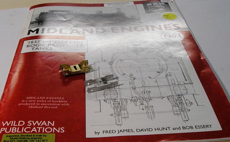
You can see the difference I think. Very much a case of making it up as I go along but the job turned out well. I need to represent a pair of leaf springs on top of the bogie - haven't figured that out yet. The slot will allow the bogie to move laterally as well as pivot. I won't be using the dreaded swing link.
The book is extremely useful, containing a large number of photos and most valuably, a great many works drawings that appear to be scaled to 1mm : 1 in.
John
 Last edit: by Brossard
John
Posted
Full Member
I measured up the spring in the drawing and then carved the shape from scrap brass. A piece of strip in the center completes the effect. None too bad, notwithstanding this cruel closeup.
John
John
Posted
Full Member
This morning, I fashioned a retention plate for the bogie by soldering a nut to it (twice, I screwed up the first time :twisted:). The plate was soldered into place and the bogie attaché by a screw:
Right now the bogie is just along for the ride. I must try to figure out a way to spring it so that it supports some weight.
I need to make some gizmos to hold the motor horizontal.
Later on, I made up the brakes and soldered the wire hangers in.
I also made some more springs for underneath the frames. Why these weren't provided beats me. This truly is a Craftsman kit since I'm having to make a lot of stuff myself.
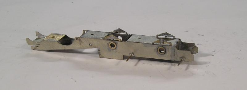
The springs aren't the best but when the chassis is assembled, they'll pass muster I reckon. You can see the retention plate for the bogie.
I looked at the castings yesterday - yecch! So often these let the kit down and this is no exception. I've been on to AGW for a chimney, dome and buffers.
John
John
Posted
Full Member
In fact the loco has 4 sandboxes which are of a quite particular shape. I used the drawing and a works grey photo in the book to guide me in the making of more accurate ones, viz:
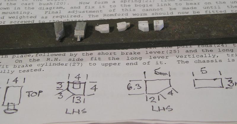
On the left are the sandboxes as supplied - huh? On the right sandboxes made from Evergreen strip. I scaled the drawing to produce the sketches, then carved the boxes. There's a filler on the center pair.
I have since attached these to the frames. Getting the location just so was quite a fiddle. I like to drill for and solder in a brass rod on which to hang things like this.
Gotta love the instructions, one long run on paragraph.
John
John
Posted
Full Member
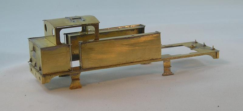
So I thought I'd make a start on the body tonight. The footplate, buffer beams, valences and footsteps were assembled:

All fiddly stuff. I got the valences on by progressively tacking and straightening until all was good. Must give it a wash now.
John
John
Posted
Full Member
Wheel tyres were cleaned. These were then trial installed with the gearbox, and footplate tried - I'm delighted that the gearbox fits within the footplate without any problems.
Coupling rods were solder laminated and chemically blackened.
Crankpins were installed in the wheels. These do need to be secured with a drop of Threadlok. (If you use CA you will not get them out again without wrecking the pin and possibly the wheel.)
The rod holes were progressively opened out until the chassis ran freely. They were temporarily held on the crankpins with pieces of wire insulation.
At this point, the chassis is in the paint shop having been primed this evening.
I also worked on the body.
The bunker was built up and installed:

Lamp brackets were installed at the back and front. These were made by bending brass strip to suit. The kit does provide some pieces of NS but these didn't work for me. I found some brass strip of the correct width in my scrap box.
Tanks were also made up and beading installed. Tricky thing this beading and it required quite some finagling to get it on straight and true. The process wasn't helped by the beading being bent and twisted. There are loops on the beading for the cab handrails.
It is very easy to get solder where it is not wanted and I spent a very great deal of time cleaning excess solder off the visible surfaces. This was done with scrapers and fiberglass brushes.
Exciting stuff!
John
John
Posted

Full Member
Doug
'You may share the labours of the great, but you will not share the spoil…' Aesop's Fables
"Beer is proof that God loves us and wants us to be happy" - Benjamin Franklin
In the land of the slap-dash and implausible, mediocrity is king
"Beer is proof that God loves us and wants us to be happy" - Benjamin Franklin
In the land of the slap-dash and implausible, mediocrity is king
Posted
Full Member
John
John
Posted
Legacy Member
Allan
Posted
Full Member
:cheers
John
John
Posted
Full Member
It doesn't look like much but there was a lot of faffing to get the tanks installed. The handrail supports had to align and in truth I had to use a 0.020" drill to cut the holes back 0.5mm on the RHS to get the handrails to be vertical - lor'!
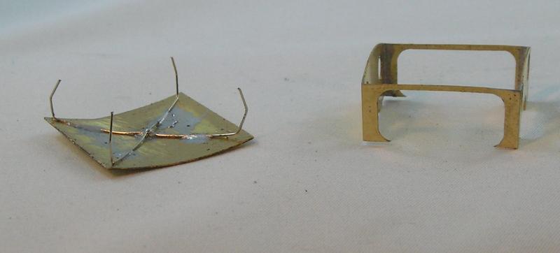
I also assembled the cab. For the roof, I get irritated when I can't access the inside so I used a dodge that Iain Rice uses which, as you can see involves soldering springy wire to the inside of the roof. It seems to work although there will be some adjustment needed.
At this point I'm supposed to solder the cab on, but I want to detail the inside of the cab so I think I'll wait for my backhead. The model as designed would have the motor in the cab - how naff!
Tony Wright in his Right Track videos (Nos 1 & 2 - get them if you see them) has some very good advice on soldering.
John
John
Posted

Full Member
Posted
Full Member
 Don't you want to join in the fun?
Actually this will be my first complete loco kit. I've dabbled over the years with chassis and upgrading RTR locos. I've got a fair few started, but for one reason or another the build stalled. I want to make some headway in getting them done.
John
John
Posted
Legacy Member
Allan
Posted

Full Member
Posted
Full Member
John
John
Posted

Full Member
'Petermac
Posted
Full Member
Skill comes from experience so you need to make a start on something small and simple. Also very helpful is some resource material on your subject - kit instructions usually have some info, but not nearly enough.
John
John
1 guest and 0 members have just viewed this.