Shelf Layout
Posted

Inactive Member
Thanks. It started out life as a workbench with a shelf under it. Now it transitions between a workbench, storage and junk storage.

There's not much to learn about DCC installation - it's just two wires!

Max
Port Elderley
Port Elderley

Posted

Banned
Posted
Inactive Member
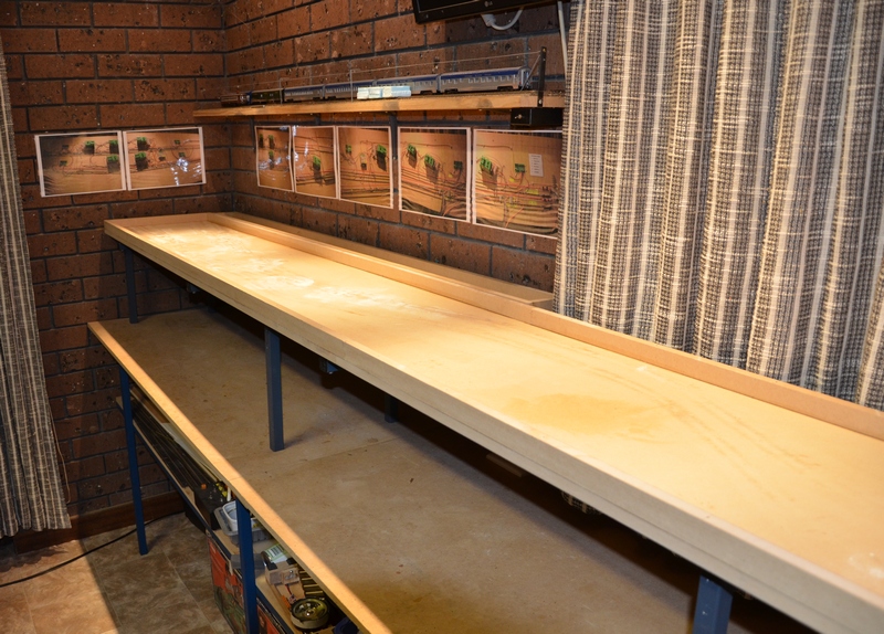
All of the old holes have been filled in and sanded off to prevent the glue from leaking out when I stick the foam boards on.
Max
Port Elderley
Port Elderley
Posted

Full Member
 :oops::oops:
'Petermac
Posted

Full Member
Posted
Inactive Member
Max
Port Elderley
Port Elderley
Posted
Inactive Member

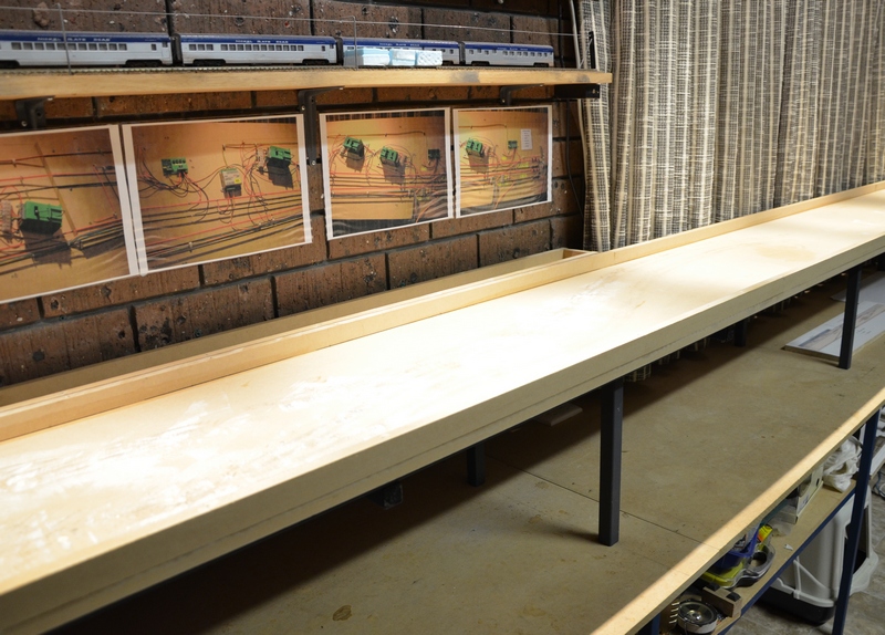
These will be lifted again and glued in.
Then place the 6 mm top boards in place, ready for marking out the track plan.

You can see how once the styrene is glued top and bottom, the foam sandwich will make a very strong but relatively light board.
Max
Port Elderley
Port Elderley
Posted
Banned
Isn't the 16mm MDF strong enough on its own, tech screwed to your sturdy frame ? Or does your method allow for some sound deadening ?
Cheers, Gary.
Posted
Inactive Member
The foam sandwich does a couple of things. It provides space under the elevated top board for the Peco turnout motors and switches. The steel frame precludes me using Tortoise or other slow motion motors. I have had to either mount the motors on top of the board or make a space below the turnouts.
Secondly, the areas where there is no track will be carved away to provide land contours and a watercourse. Part of the purpose of this layout is to gain a pass in the NMRA Achievement Program in the Subject of Building Scenery. I have enough kit bashed buildings on my main layout, but to complete the qualification, I have to scratch build another three buildings, one of which has to be a bridge.
Having 30 mm of foam plus the 6 mm of MDF top board should be plenty of height to accommodate a trestle bridge under the main line. The watercourse will run back to the next set of tracks, where it will disappear into a culvert.
I'm not sure how much you know about the NMRA AP, but participants who achieve passes in seven subjects are finally awarded the degree of a master modeller (MMR). I can't remember exactly how many there are at present, but I think it's less than a thousand world wide, and only a handful in Australia. I only have three subjects so far, so I doubt that I will ever complete the seven, but it's a fun sideline.
The layout will be controlled by RailRoad&Co software. This is an expansion of an earlier, simpler RR&Co TC layout, where I'm hoping to have multiple locos shunting boxcars at the same time and maybe eventually the odd loco just running about. It seems like a good opportunity to combine at least two challenges at once.
Sorry it's a bit long winded, but there is method in my madness.
Max
Port Elderley
Port Elderley
Posted
Banned
Cheers, Gary.
Posted
Inactive Member
I have consulted the Orifice - sorry, Oracle. Sol tells me that there are 550 world wide and 18 in Oz.I can't remember exactly how many there are at present, but I think it's less than a thousand world wide, and only a handful in Australia.
Thanks, Sol. :thumbs
Max
Port Elderley
Port Elderley
Posted
Inactive Member
Max
Port Elderley
Port Elderley
Posted
Inactive Member
Here's the first one.
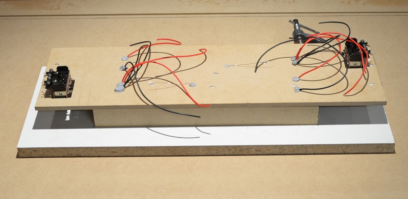
The track is held on by track pins which are bent over and covered with PVA glue. The Blu-tack is plugging the holes which have been filled with PVA from above. Once the top has set up, the Blu-tack will be removed and the bottom filled. That should prevent the wires from breaking off due to being bumped.
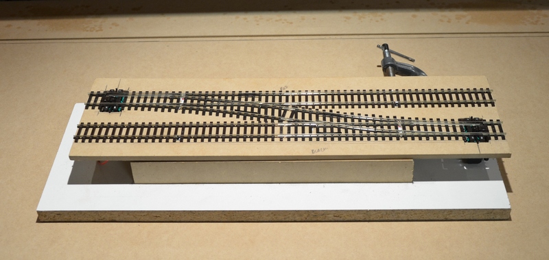
Here's the top side. The module sits on a jig which is the same size as the sides of the shelf, to check the clearance under the motor switches.
I still have to make cover plates for the turnout motor hatches. Then the assembly can be tested to make sure the frogs are being switched correctly and that the DPDT switches are adjusted correctly.
I have to say that now that I've assembled two units, I don't really understand why they would give trouble.
Time will tell, I suppose.
Max
Port Elderley
Port Elderley
Posted
Full Member
Hoping that I am not tempting fate, but I have not had a single problem of any kind. I took the same sort of care as you seem to be taking on the installation, and I think that must help. Incidentally, almost all of mine are fitted directly to the underside of the points - like you have done - and I find that they do not make the loud bang people talk about, when they operate. It is much more of a gentle click - maybe not as graceful as a slow motion motor, but that doesn't worry me.
I have had to mount a couple of them directly onto the top surface of the baseboard and use wire in tube to get to the point tie bar, and they do make a bang when they operate.
By the way, I hope you are liking working with the 50mm polystyrene board? I used the same thing for a 7ft by 3ft N gauge layout I built with my grandson. It is in two pieces which slot together, and is stored under my main layout. We built it several years ago, and it has remained remarkably stable, despite some rough handling during assembly.
Posted
Inactive Member
The board is high density styrene offcuts from a company here who specialise in bespoke styrene orders. It's actually 30 mm but cut by a machine and very accurate. The boards were 2010 x 600. I lost a bit when I cut them, but at A$10.00, I thought it was still good value.
I'm sure the offcuts will be put to good use later.
78 motors! You must have started when you were very young.
Max
Port Elderley
Port Elderley
Posted

Inactive Member
If memory serves, I have had only 5 P-motors fail in that time.
My home layout has 72 PL10 P-motors of which several have the PL13 (cheap) SPDT slide switch attached which also work very wel.
With exception of 6 my PL10s are surface mounted covered with scratch built linesides huts. Some are mounted at 90% angle to point, some are connected with brass rod in tube.
I have only ever powered my P-motors with AC voltage both before and after op points through DCCand never used CDUs.
Pl10s do require more than 12v to operate reliably. Before DCC I found 18vAC fired Peco P-motors well with no damage.
OP points with DCC I have always used Lenz LS150 accessory decoders powered with 18V AC which works very well even op 2 points in tandem IE cross overs.
Recently I installed a DCCconcepts AD-S8 accessory decoder op Peco PL11 side mount P-motors which seem to work very well.
The AD-S8 is powered by the DCC bus each of the 8 units on the S8 has its own CDU.
Current draw is only milli amps and takes 1/2 second to recharge.
Cheers
Ian
Any DCC is better than no DCC
Posted
Inactive Member
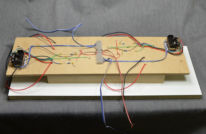
I got to this point last night and my brain seized up.
I'll have another look tonight. It will be something simple - probably me.The up side.

The little indicator LEDs work - so that's something. ;-)
Max
Port Elderley
Port Elderley
Posted
Full Member
The wiring is now complete - except that I've stuffed something up and every rail is connected to every rail in each turnout. :
I suppose that you did remove the factory fitted links under the points between the switch blades and the frog??
From here, I cannot see anything obviously wrong with your wiring.
Posted
Full Member
Such a pity it doesn't work …………………
;-)
'Petermac
Posted
Inactive Member
I should have kept my counsel, but I like to tell it warts and all.
Fortunately it's easy to unsolder each connection. It might be the switch. The one for the LEDs took a bit of adjusting.
The tolerances around the mounting bolts are pretty big.
Thanks, Peter. It's my first use of the hot melt glue gun.
It's much quicker than PVA, but you end up with a lot of spiders' webs.
Not sure if I really like it.
Max
Port Elderley
Port Elderley
1 guest and 0 members have just viewed this.