Small layouts planks and micros

Post

Posted
Rating:
#226286
Avatar
Full Member

Making a mimic panel or unable to

[user=606]Sol[/user] wrote:
OK, Petermac, what is with the flashing LEDs then ? Can't the system makes its mind up?
I've always been a bit of a ditherer Sol ……………….. ;-)

Max is right - once the point has changed, the new route LED is steady.  At first, I thought it was a sort of copy of the crossing barriers which flash alternately whilst they close but I really don't know why they flash.  Maybe just to tell me it's moving something, or, just that it looks good ……………… :cheers

'Petermac
Online now: No Back to the top

Post

Posted
Rating:
#226304
Avatar
Full Member
Hi Petermac.  Bravo, Bravo it looks fine to me, Alas I cannot follow your fine example with my manual points, and I was never one for modernisation , a bit of a Luddite ? But I do admire your system. And safety must come first.would you please tell me about the power consumption of the LED's and would I be able to " do my own thing"? By making aPluggable Mimic board? Connected to the DPDT slide switches that are doing the job of point Motors .
My rough plan is using the spare terminals on the switches with a power supply, resistors, and suitable LED's, with either built in sockets on or under the baseboard ( of course they would have to be hidden,from view) but which connectors are best ? I have a plan for the panel , it looks just like your one, only compact .
Please advise. Kevin

Staying on the thread Kevin.
Online now: No Back to the top

Post

Posted
Rating:
#226305
Avatar
Full Member
LEDs consume almost no power Kevin - mine are 12 volts but only use milliamps of power.  My panel has a dedicated 12v regulated supply but that's because the Mega Points controller requires a steady supply. For LEDs, any old supply will do but the resistor is critical otherwise they'll blow instantly. 

I see no reason why you can't use your DPDT switches with an LED wired to them via the resistor.  My panel mounted LEDs came with a "normal" wire attached (plain LEDs usually have 2 plain wire "legs" for connections).

Having wires already attached, they could be connected to the "circuit" either by soldering, choc blocks or in fact, any kind of connector you care to use.  It's just like connecting any wire to another - do it how you choose to.

Naturally the panel mounted LEDs are more expensive that the plain ones but they are very robust.  I'll post a photo of one later so you can see what you're paying for.

'Petermac
Online now: No Back to the top

Post

Posted
Rating:
#226306
Avatar
Full Member
Hi Petermac.  Thank you, but I will have to get some advice on the socket connection , between the baseboard and the panel.  All the best. Kevin

Staying on the thread Kevin.
Online now: No Back to the top

Post

Posted
Rating:
#226828
Avatar
Full Member
Hi Max   I have hit a snag ( not a sausage ) with my mimic panel, "interconnectivity?" I have cobbled together my panel, purchased the LED's,  15 pin plug and socket (but I am only using nine pins) all ready and waiting, but,:hmm I cannot find a suitable "9 Core cable" for a tidy connection between the baseboard and panel, I have looked on eBay without any luck, I know there are many experts on YMRC, but I remember your thread on baseboard wiring.
I thought of nine different coloured wires and binding them with cable ties, or heat shrink tubing but that may not be satisfactory ? Have you got any good ideas or know where I am able to make such a purchase , as I only require about a yard (or a metre), all the adverts that I have seen quote one hundred metres or more.
   All the best. Kevin

Staying on the thread Kevin.
Online now: No Back to the top

Post

Posted
Rating:
#226829
Sol
Avatar
Site staff
Sol is in the usergroup ‘Super-moderators’
Kevin, most electronic shops sell it by the yard/metre but you have to go there.

Ron
NCE DCC ; 00 scale UK outline.
Online now: No Back to the top

Post

Posted
Rating:
#226830
Avatar
Inactive Member
Hi Kevin

For applications like this, I use rainbow cable.

Ribbon cable - Wikipedia

Available at your local electronics store.

Cheers
Online now: No Back to the top

Post

Posted
Rating:
#226832
Avatar
Full Member
Hi Ron.  Thank you for your reply. My local electronics shop "Maplin" is a suitable candidate, but, the staff are a bit vague? Unless one knows the exact product? They seem useless, and cannot give advice. If I find what I'm looking for and I am likely to need another one, then I keep the packet and take it with me the next time.  All the best. Kevin

Staying on the thread Kevin.
Online now: No Back to the top

Post

Posted
Rating:
#226833
Avatar
Full Member
Hi Max.  Thank you for your reply. I have never heard of ribbon cable. Does that carry 12volts for model railways without any problem? and can I separate the ends to wire it to a "Terminal Strip"? I will have to google that and I will let you know how I get on.  All the best. Kevin

Staying on the thread Kevin.
Online now: No Back to the top

Post

Posted
Rating:
#226834
Avatar
Inactive Member
Yes.  It's easily separated as described on Google.

It solders well and will easily carry LED current.

I've even used it for CDU's.
Online now: No Back to the top

Post

Posted
Rating:
#226835
Avatar
Full Member
Hi Max.    Thank you again. But, it has occured to me that flexibility may pose a problem, where the cable connects to the plug, by design the cable is " a loose wire", flying about, whereas if it was fixed in position the wire are less likely to pull out or fracture, could you comment on this?  All the best. Kevin

Staying on the thread Kevin.
Online now: No Back to the top

Post

Posted
Rating:
#226837
Avatar
Inactive Member
If you're soldering a gang of nine wires to the device, each will support the others.

If I've stripped them apart, I will usually put a cable tie around them for support.

That's usually enough.
Online now: No Back to the top

Post

Posted
Rating:
#226838
Avatar
Full Member
Hi Max.  Thank you again.  Kevin

Staying on the thread Kevin.
Online now: No Back to the top

Post

Posted
Rating:
#228258
Avatar
Full Member
Hi Petermac.   My  very basic manual mimic panel has been a long time coming? Now that is just about ready.But to improve it? I went to my local Maplin branch and purchased a VGA 1.5 Extension Cable, Male to Female       (as opposed to my original idea of one end being wired to the panel and the other end flying loose with a plug on it).       But it didn't work, Why?
I ask myself. Then I decided it couldn't be my wiring? it must be the extension? Then I inspected the Extension and Lo and Behold it only has 14 pins. I didn't need 15 pins, but wouldn't you know it, one of the pins I chose was the absent one, number 9 as it is present with the original "Male Plug". Maybe I should have stuck with my 5-5-5 plug and socket
Has anyone come across this before??    All the best. Kevin


Staying on the thread Kevin.
Online now: No Back to the top

Post

Posted
Rating:
#236453
Avatar
Full Member
Hi Petermac , Max ,  Ron , and interested parties. Back to my “Mimic Panel “ manually operated of course , as soon as I it to work , I am now going to change it. Instead of a wooden box, with LED’s , I intend to fit a plastic panel and a paper diagram. With holes for the LED’s. But I have read about a “Superior alternative to Perspex” would any of you fine Modellers please advise me on this screen.   Best wishes. Kevin

Staying on the thread Kevin.
Online now: No Back to the top

Post

Posted
Rating:
#236690
Avatar
Full Member
Hi Petermac     Over the weekend? and a bit more? I have purchased a piece of clear plastic, drilled the holes for the LED’s, put masking tape.  for my track plan, and sprayed with a rattle can a grey primer ( Halfords ) meant for plastic . Now I have removed the tape it looks too clear? And I intend painting over the grey primer with a translucent orange colour? ( do you think that this is a good choice of paint ?) to represent the Panel used in a signal cabin with one difference, it will not show train passage.The old Mimic Panel worked ( manual ) no flashing lights) but I wanted to update the “ plain wooden box” .
Best wishes. Kevin

Staying on the thread Kevin.
Online now: No Back to the top

Post

Posted
Rating:
#236736
Sol
Avatar
Site staff
Sol is in the usergroup ‘Super-moderators’
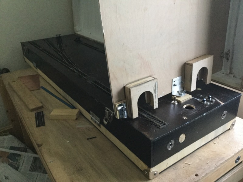
Kevin, this is the photo you sent me assuming it is your plank…


Ron
NCE DCC ; 00 scale UK outline.
Online now: No Back to the top

Post

Posted
Rating:
#236739
Avatar
Full Member
Hi Ron.    Thank you . Your assumption is correct , that is the four foot by fourteen inch plank, the other one is nine inches wide. The view is of the rear view of the “ Scenery Break “ , and the WIT DPDT Slide switches can clearly be seen alongside the programme track isolating switch . But there is lots to do with the scenery, but the trains run well, when I can keep awake?  Best wishes.  Kevin

Last edit: by Passed Driver


Staying on the thread Kevin.
Online now: No Back to the top

Post

Posted
Rating:
#236761
Avatar
Full Member
Hi Ron , Max , Petermac , and interested parties?Thank s to Ron , I have discovered that taking photos of a Model Railway with an iPad , in natural light is pushing ones luck? And got me to thinking , rather than having the lights on, what about illuminating the layout with low voltage / wattage lighting, similar to LED coach lighting? Then I googled my idea. And I found that a lot of Modellers over think things. Is there a simple way.? To light up the baseboard ?  Best wishes. Kevin

Staying on the thread Kevin.
Online now: No Back to the top

Post

Posted
Rating:
#236762
Avatar
Inactive Member
Hi Kevin

I just went to IKEA and bought a couple of standard lamps and mounted both booms on the one mast.

Cheers
Online now: No Back to the top
1 guest and 0 members have just viewed this.